6502 Breadboard Simulator
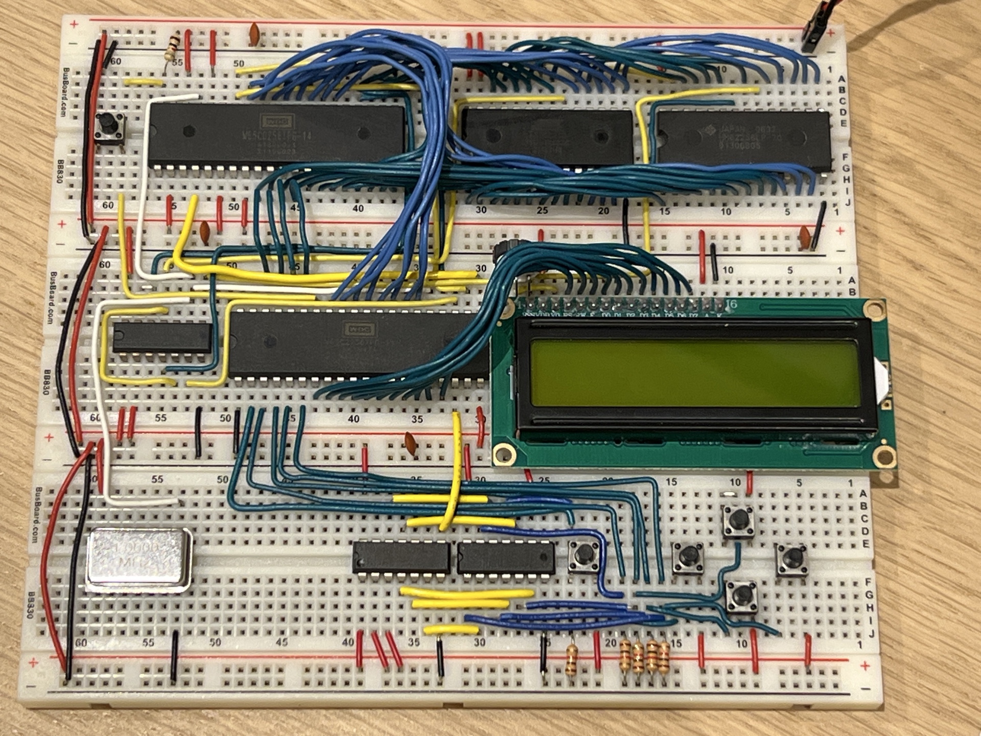
In-browser 65C02 + 65C22 VIA + 16x2 LCD emulator with the real wiring.
About the 6502 + VIA + LCD breadboard simulator
This is the same 65C02 + 65C22 + HD44780 wiring used on the physical breadboard. Programs talk to the LCD through VIA PORTB (data) and PORTA (E/RW/RS), and read button input on PORTA bits PA0..PA4. Load an example below, press RESET, and run or step to see the LCD light up on the board.
A processor is a tiny decision-maker inside a computer. It follows a list of steps called a program, like a cook following a recipe. Its rhythm is always the same: it reads one instruction, understands it, acts on it, and repeats, many times each second, even in very small machines today.
To make those steps work, the processor uses memory, which you can picture as a huge row of numbered mailboxes. Each mailbox has a number, which is the address, and it can hold a small piece of information, which is the data. The processor keeps going back to these boxes to pick up new instructions and to store results. Memory itself is passive; it just waits for the processor to ask.
The processor and memory are connected by two shared roads made of wires. The address bus is the road that says which mailbox number the processor is talking about. The data bus is the road that carries the actual data that is being read or written. There are also simple control lines that act like traffic lights, telling everyone whether the transfer is a read or a write and when it should happen. Because the roads are shared, timing matters, just like cars taking turns at a narrow bridge.
Imagine a read step. The processor chooses an address, puts that number on the address bus, and sets the traffic lights to "read." Memory sees the address and responds by placing the data on the data bus. The processor then takes that data in, like asking a librarian for a page number and receiving the word on that page. For a brief moment the data sits on the road, then it is safely inside the processor.
A write step is similar but goes the other way. The processor chooses an address, puts it on the address bus, and also places a value on the data bus. Then it sets the traffic lights to "write," and memory stores the value in that mailbox. It is like dropping a letter into a mailbox so it can be found later. Because the data bus is shared, only one side should "talk" on it at a time.
Inside, everything is made of tiny switches that are either off or on, which we write as 0 or 1. Eight switches together form a byte, a small package of information. For example, 00000001 means 1, 00000010 means 2, and 00000011 means 3. The same eight bits can also represent a letter or part of an instruction, depending on how we interpret them.
An instruction is just a small number that means "do something." Often it is followed by extra bytes that say with what value or from which address. You can imagine a tiny story like "take the number from mailbox 200, add 3, and store the result in mailbox 512." On their own they seem small, but together they build the whole behavior, like notes making a song. Each of those actions is guided by simple instruction numbers.
Inside the processor are a few small places that hold numbers, called registers, which are like fast pockets. There is also a small calculator that can add, subtract, or compare. A special pointer, called the program counter, acts like a finger showing the next mailbox to read for the next instruction. The processor also keeps little notes, called status flags, that say things like "was it zero?" or "was the number too big to fit?"
Put it all together and you get the full loop. The program counter points to the next instruction in memory, the processor reads it using the buses, and it may read more bytes if needed. It updates its registers, maybe writes a result back to memory, and then the program counter moves on. This constant loop is how all software behavior is built, step by step.
The 6502 simulator slows this down so you can watch it. You can see which address is on the address bus, what data is moving on the data bus, which registers changed, and how the program counter moves. That makes the invisible traffic inside the chip visible, so learning becomes much easier and more concrete.
Firmware Editor
VASM-style 6502 assembly. Assemble to ROM at $8000.
How to use this simulator
- Pick an example or edit the program in the editor.
- Press RESET on the breadboard to load it into ROM.
- Run, or Step Instruction to execute a single opcode.
- Use the buttons to send input on PORTA (PA0..PA4).
- The LCD output appears on the breadboard image to the right.
Breadboard + LCD
Real wiring reference with live HD44780 output. 5 + 3 - 2 = 6
- 1 Reset
- 2 Clock
- 3 Step/Run
- 4 Watch buses
- 5 Inspect
Interface guide
- Press RESET on the breadboard to load the program into ROM.
- Pick a clock mode (1 MHz, 50 Hz, or STEP).
- In STEP mode, use Step Instruction or Run/Back cycles to move instruction by instruction.
- Watch the Address/Data/RW buses light up as bytes move.
- Click a chip (CPU, EEPROM, RAM, VIA) to open its live detail panel.
What the buses mean
- Address shows which memory location is being accessed.
- Data shows the byte being read or written.
- R/W tells you whether it is a read or a write.
Step mode tips
The "Executing now" panel highlights the current instruction. Click a line to see its cycle count and which memory ranges it touches (ROM/RAM/VIA).
Each chip shows its last access in real time. The EEPROM label under the chip tells you which firmware is loaded.